LAN Device Review
One thing that can be very overwhelming to people coming into the networking field is the sheer number of different devices that exist throughout the Local Area Network (LAN). This can be especially confusing when the first network environment that a new engineer is put into has older and newer devices; this is because many modern devices combine many of the functions that existed within older individual devices. This article takes a look at the common devices that are seen on a modern network and provides a description of how some of these device functions have been combined over the last 20 years.
LAN Devices
As mentioned in the overview, there are certainly a number of different devices that will be seen throughout the LAN. Of these devices, there are a couple different device types that exist throughout almost every LAN in one way or another.
Hub
One of the oldest types of LAN devices is the hub; a hub provides a method of connecting multiple network devices through a single device. Individual network devices could be cabled into the hub and all signals coming from each device would be echoed to all other connected network devices. 20 years ago this was not a problem as a shared media was able to provide enough service quality to make most network devices happy. However, in modern wired networks a shared media would greatly decrease the efficiency and capacity of the network; hubs are generally limited to 10 Megabits per second (Mbps) of traffic that is spread across the entire shared network. On most modern networks hubs have been replaced by switches which will be covered in a future section. Figure 1 below shows an example of a hub:
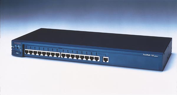
Figure 1 Hub
Bridge
In older networks where most networks were connected, a method was required to separate the different networks from each other at the physical layer. Hubs simply repeated all traffic in and out of each port, and thus provided no separation between devices. This is where a Bridge came in; a Bridge provided a mechanism that allowed Layer 2 connectivity between two networks but did it without having to reflect all traffic at the physical layer. Once the devices from each side of the bridge were mapped, only the traffic that was destined for devices on the other side of the bridge and broadcasts would be transmitted. A bridge also provided a method of separating the LAN into different collision domains. One big disadvantage of the shared medium that a hub provides is that it is possible for multiple devices to attempt to communicate on the network at the same time; when this happens a collision occurs. When a collision occurs, each device will stop transmitting, back off, and wait a random amount of time before checking the status of the LAN again and repeating the process of attempting to transmit on the network. This process takes a lot of time and can greatly reduce the effectiveness of the network; this is why most modern wired networks no longer use shared techniques. Figure 2 below shows an example of a bridge:
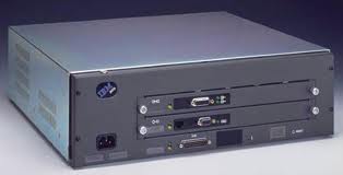
Figure 2 Bridge
Switch (Layer 2)
A Layer 2 Switch essentially provides the functions of a bridge in the same form factor as a hub. Switches are often seen in modern networks and are placed in the network where the Hubs were 20 years ago (and may still exist in some networks). Each port on a switch provides a separate collision domain and is typically only connected to a single end device. Modern switches can provide over a Gigabit of traffic per port on the switch, far exceeding the capabilities of the hubs of the past. Figure 3 below shows an example of a Layer 2 switch:
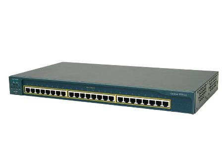
Figure 3 Layer 2 Switch
Router
A router is a Layer 3 device that enables traffic to be sent between different Layer 2 networks. It is possible for very small businesses to have all of their network devices on the same Layer 2 network, this is a perfectly valid solution when the devices are trusted and the amount of traffic is limited. However, in larger networks the separation of Layer 2 networks is built in to both increase security (by providing separation) and efficiency. This separation is provided by a router; the router not only provides the ability to control where traffic is allowed but it also provides a way of creating multiple broadcast domains. A broadcast domain is simply a group of devices that can “see” Layer 2 broadcasts from all other members of the group. Figure 4 below shows an example of a router:
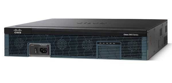
Figure 4 Router
Switch (Layer 3)
One of the things that can get very confusing for individuals new to the network field is the difference between a Layer 3 switch and a router; the easy answer is that there is no functional difference. Each device is able to perform the duties that have been traditionally referenced to a router. Where they do differ is in the amount and type of interfaces supported, the amount of total throughput available and the number of features supported. A router traditionally has a limited number of total interfaces but typically supports many different types of interfaces; both LAN and WAN. A Layer 3 switch typically has more interfaces that are limited to Ethernet and has a much higher total throughput capacity. Figure 5 below shows an example of a Layer 3 switch:
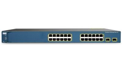
Figure 5 Layer 3 Switch
Summary
There are certainly many different devices that will be seen throughout the career of a network engineer. The purpose to this article is to give the entry level engineer a review of the most commonly deployed devices and how they operate within the LAN. Many other devices can exist within the LAN that look very similar to the devices shown in this article but differ greatly in function. When starting out, it is best to do as much research as possible about the devices that are used within the network, what specific devices are used within the organization, and learn their function, specifications, and configuration (if possible).This knowledge will accelerate the understanding of how the network is built and how best to work with it. Hopefully the content of this article will help those engineers getting into the field and help in their learning.